|
|
Post by tjohansen on Feb 27, 2016 14:30:31 GMT
Hi trying to understand the diagram from github.com/computourist/RFM69-MQTT-client/blob/master/DHT%20end%20node/DHT-node.pngSince I dont know much about wiring and diagrams I'm getting more comfortable when I have a breadboard diagram. So trying to make one of the Endnode with DHT11. Dont know if its gonna be 9v battery driven or pluged but does it change anything? I hope you will correct me if I have done anything wrong here (not all the component icons are correct thats why I have labelled them): 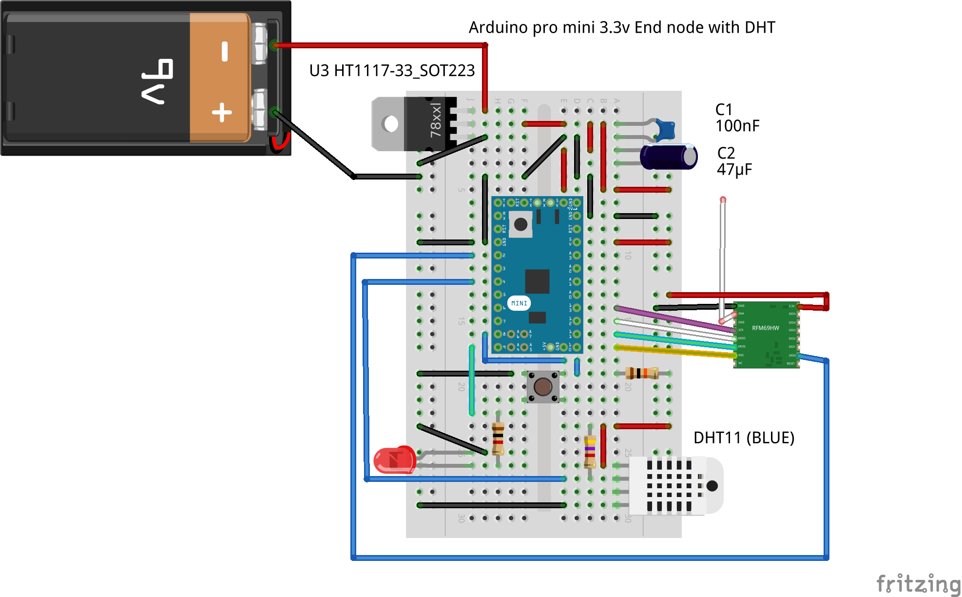 Some of my worries are: - I don’t know how important it is to make the GND to C1 to C2 to GND its own circuit, or if I could use any place to connect to GND. - I haven’t placed the switch button in the same GND circuit, would that be a problem? |
|
|
|
Post by tjohansen on Feb 27, 2016 14:34:17 GMT
|
|
|
|
Post by papa on Feb 27, 2016 15:02:01 GMT
Yes, until we get more comfortable with schematics, physical layouts do help. But best to get used to the schematics. Sometimes, it's all we get. In the Sep 23, 2015 at 11:11pm post in my Success... thread, I made some comments (from a near newbie perspective) about schematics that might help you some. Using just the pic, I did not check all your connections, but will respond to the specific questions you asked & what I can see in the pic. 9 volt battery vs wall adapter? Should not matter as long as you stay within the limits of the voltage regulator's input. I don't claim to be an electricity / electronics expert. About the 2 GND questions: My understanding is that as long as GND connection traces back to any GND on the Arduino compatible, you ARE in the same GND circuit (as you need to be). Sometimes (for better results) assembly instructions specifically recommend to use a GND connecting point on the Arduino that is as close as possible to the Arduino's power connector. Absent such specifics, it does not seem to matter. I recommend you be especially careful, even paranoid, about power & GND connections which can do harm (on power sources like regulators & inputs on components). Other things don't cause damage & can be corrected. Without loading the fritzing file & just looking at the pic: Looks like voltage regulator (according to the part # you listed), push button, & DHT11 are wired correctly. Looks like C2 still needs a GND connection, but seems you were waiting until you got an answer. My understanding is that the capacitors act like filters to help smooth the power in the circuit. On the pic, I cannot see the RFM69 labels to check that close. They look like they might be wired ok. Again be very sure about GND & power connections & other mistakes should be fixable & not cause harm. |
|
|
|
Post by tjohansen on Feb 27, 2016 16:16:25 GMT
Valuable feedback papa.
the C2 was a mistake, I forgot to GND :-) thx for pointing that out, will correct it.
The RMF69 is correct, im not worried about that.
|
|


