kmccb
New Member

Posts: 10 
|
Post by kmccb on Oct 25, 2015 18:43:40 GMT
Just spent like $100 on all the parts so hopefully someone can help me lol.. I just soldered a RFM69HW and connected it to my UNO and I'm trying to get "Gateway_RFM" loaded.. I downloaded the .ino file but when I try to verify it I get:
"Gateway_RFM.ino:28:19: fatal error: RFM69.h: No such file or directory
compilation terminated.
Error compiling."
I can't even get past step 1!!
Help! Thanks
|
|
|
|
Post by computourist on Oct 25, 2015 19:24:00 GMT
Make sure you install all libraries, as described in this post. Also do not forget to change the w5100.h file, as described in the header of the sketch. |
|
kmccb
New Member
Posts: 10
|
Post by kmccb on Oct 26, 2015 1:32:38 GMT
Thanks much for the reply.. Got the Gateway_RFM verified and loaded..
Moved on to the Gateway_Ethernet.. Downloaded the PubSubClient library as instructed and tried a verify.. I now am getting this.
Arduino: 1.6.5 (Windows 8.1), Board: "Arduino/Genuino Uno"
Gateway_Ethernet:28: error: 'PubSubClient' does not name a type
Gateway_Ethernet.ino: In function 'void setup()':
Gateway_Ethernet:67: error: 'client' was not declared in this scope
Gateway_Ethernet.ino: In function 'void loop()':
Gateway_Ethernet:128: error: 'client' was not declared in this scope
Gateway_Ethernet:207: error: 'client' was not declared in this scope
'PubSubClient' does not name a type
This report would have more information with
"Show verbose output during compilation"
enabled in File > Preferences.
|
|
kmccb
New Member
Posts: 10
|
Post by kmccb on Oct 26, 2015 2:00:22 GMT
|
|
|
|
Post by papa on Oct 26, 2015 21:26:25 GMT
Yes, kmccb, CompuTourist notified us of the updated Gateway at his thread Release 2.3 Gateway. Thanks, CompuTourist! |
|
kmccb
New Member
Posts: 10
|
Post by kmccb on Oct 27, 2015 18:55:30 GMT
So wait.. In the instructable there is a Gateway_Ethernet.ino and a Gateway_RFM.ino.. Which ino is getting replaced with the gateway 2.3 and is the other one still to be used?
Thanks
|
|
|
|
Post by camblonie on Oct 27, 2015 23:25:27 GMT
They become one. Neither of the original instructable sketches are used. You need the new nodes too.
|
|
kmccb
New Member
Posts: 10
|
Post by kmccb on Oct 28, 2015 18:16:24 GMT
Ugh... So the design with the wireless module / soldering is different now?
|
|
|
|
Post by lhw455 on Oct 28, 2015 19:32:39 GMT
Ugh... So the design with the wireless module / soldering is different now? If you followed the gateway design from computerist the hardware design should be the same for 2.2 and 2.3 gateway - the instructables, as I understand it, was used as a basis for the designs you see on this forum. |
|
kmccb
New Member
Posts: 10
|
Post by kmccb on Oct 31, 2015 14:44:15 GMT
For someone who is good at following directions, but bad unless they are very specific, what do I need to modify? This is what I followed.. Create Arduino Gateways Components Needed: Two Arduino Uno Clones with 3.3V/5V switch set to 3.3V. One Wiznet 5100 ethernet shield One RFM69HW w/ wires soldered on One Arduino will be designated the "RFM Gateway" and the other is the "Ethernet Gateway". On the RFM Gateway Arduino, wire up the RFM69HW like you see in the wiring diagram at the top of this step. RFM69HW To Arduino NSS to Pin 10 MOSI to Pin 11 MISO to Pin 12 SCK to Pin 13 GND to Ground 3.3V to the 3.3V header DI00 to Pin 2 (interrupt) Plug the ethernet shield on the "Ethernet Gateway". Hook together these two gateway Arduinos for I2C using male-male dupont cables, or just hookup wire if you have some around: Ground to Ground Analog Pin 4 to Analog Pin 4 Analog Pin 5 to Analog Pin 5 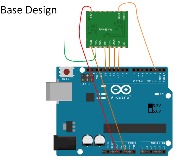  |
|
|
|
Post by papa on Oct 31, 2015 16:58:21 GMT
Looks like you're trying to follow the gateway(s) design in the original Uber Home Automation Instructable, which you can if you want. However I believe most of us have moved on to the CompuTourist-described ONE gateway & nodes which are reliable & bi-directional. This one gateway combines the two Instructable gateways & the network communicates reliably bi-directional. From your above comments, you seem to be put off by CompuTourist's latest updates which are not complete yet. From my experience, this project is doable, but takes much care, patience, & often troubleshooting. I recommend that you start with the Gateway 2.2 program sketch (its schematic is with Gateway 2.1) & the DHT Node 2.1 (schematic & sketch). These work together & could give you a reliable start. As lhw455 said, looks like the Gateway 2.3 schematic is the same as 2.2, just the programming will change, but it will need nodes designed to work with Gateway 2.3. Since you are using the switchable clones, I further recommend you look at how I adapted CompuTourist's schematics for these clones. These schematics are in my Success... posts, Oct 8, 2015 at 6:40pm & Oct 15, 2015 at 10:32am. In those Success... posts, I try to give very specific step by step ways to achieve the whole project, including the gateway & dht node. When you connect the RFM69 transceivers to the clones, be careful that for the GATEWAY, NSS connects to Arduino D8. However for the Nodes, NSS connects to D10. This approach will use only one of your clones (plus w5100 Ethernet Shield on top) for the Gateway & you can make the other clone into a node. |
|
|
|
Post by lhw455 on Nov 1, 2015 10:00:30 GMT
Just to add to what papa is saying, you are where I was a few months ago. Some basic advice 1) You want to start with building the gateway, for this you need an Arduino clone, and Ethernet shield and an RFM69 (H or HW) plus some wires and tools (plus 2X LED and resistor if you want some activity/connection indicators) 2) For the node, I started with a simple temperature/humidity node (which I haven't gotten around to completing yet) - this requires and Arduino clone, another RFM69 (H or HW), a DHT sensor and some wires and tools (plus a resistor or 2 and optionally a switch) All of this you should find in my newbie post. For both of the above, download computerist's sketches from the github location mentioned in my newbie post - this contains the the sketches and wiring diagrams - some wiring diagrams are in the post themselves, which I found easier to use. Also, you'll have questions about the wiring, again my post has many of the answers. Final note: as papa says, you can pretty much ignore the original instructables documentation, these have been superseded which what I understand to be better versions of the hardware/software. The pictures you posted above are from the instructables. |
|
kmccb
New Member
Posts: 10
|
Post by kmccb on Dec 5, 2015 17:15:58 GMT
I gave up on this.. If anyone is interested in some boards, wifi stuff, etc let me know and I'll post what I have to sell..
|
|
|
|
Post by papa on Dec 6, 2015 22:10:57 GMT
kmccb, sorry you had a bad experience with this. I've said before that this project takes much patience & perseverance, but is rewarding if one can see it through.
Nice of you to offer to sell your parts. I would check to see if proboards policies permit sales.
|
|


